Skip to content
DE|EN
+41 55 511 50 85 Request a quote →
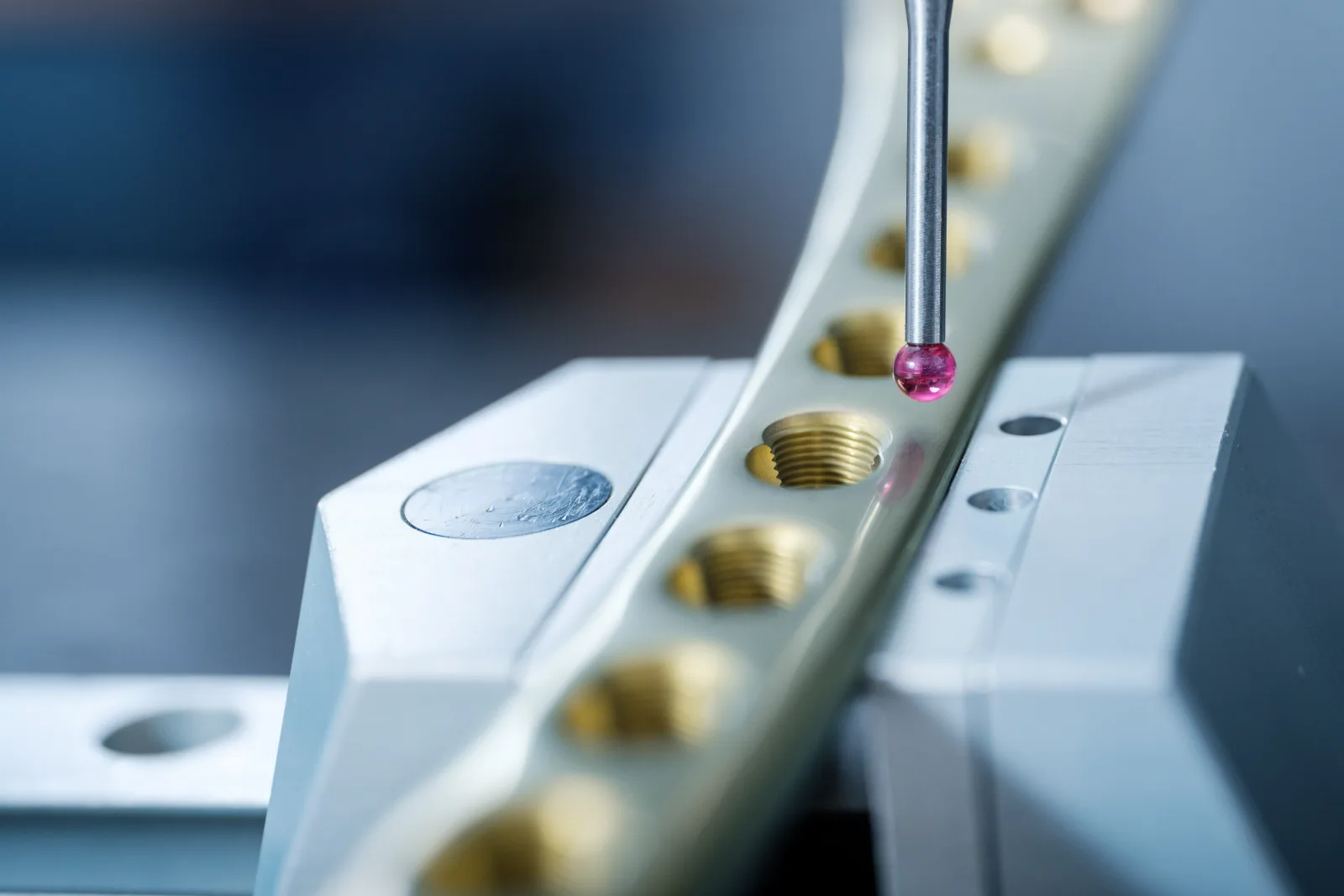
Tactile measurement: ruby stylus probing threaded holes on an elongated part
Measurement method

Tactile 3D coordinate metrology

The reference method for regular geometry and the tightest tolerances. Measured in the temperature-controlled measuring room at reference temperature per ISO 1, or on your machine.

Describe your measurement task

What we measure tactilely

Probed by contact, point by point or scanning. For tolerances and datum systems that demand the highest confidence.

Regular geometry with the tightest tolerances: size, form and location per ISO GPS
Datum systems cleanly set, for comparable and reliable results
Measurement uncertainty evaluated in accordance with ISO 15530-3 using calibrated workpieces
Can be combined with optical sensors in the same inspection plan
Performance data

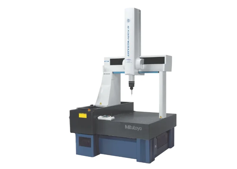
Mitutoyo Crysta Apex S776 — our reference system

System
CNC coordinate measuring machine with scanning and touch-trigger probes, single points to full-surface scanning
Length measurement error
down to (1.7 + 3L/1000) µm
Measurement uncertainty
per ISO 15530-3 (k=2): distance 100 mm ±2.0 µm · diameter 50 mm ±2.0 µm · all characteristics
Form and location
(k=2, one stylus position): roundness ±2.5 µm · straightness ±2.5 µm · parallelism and perpendicularity ±2.0 µm
Software
Mitutoyo MCOSMOS and MiCAT Planner — CAD-based programming, PMI evaluation, customised measurement reports
Mitutoyo Crysta-Apex bridge-type coordinate measuring machine in the measuring room

Measurement uncertainty per feature

Expanded measurement uncertainty U with a coverage factor of k = 2, evaluated with a calibrated workpiece to ISO 15530-3 and assessed to the GUM (ISO/IEC Guide 98-3). The coverage interval is roughly 95 percent. The number of stylus positions is stated because each position is qualified separately and adds its own uncertainty to the result. With several positions the uncertainty is therefore usually higher than with one. All values are rounded up to 0.5 µm.

Size dimensions
Nominal
Stylus positions
U (k = 2)
Distance
25 mm
1
3.0 µm
Distance
100 mm
1
2.0 µm
Distance
200 mm
1
3.0 µm
Diameter
Ø50 mm
1
2.0 µm
Diameter
Ø100 mm
1
2.0 µm
Form tolerances
Nominal
Stylus positions
U (k = 2)
Symbol for Straightness
Straightness
–
1
2.5 µm
Symbol for Flatness
Flatness
–
1
3.0 µm
Symbol for Roundness
Roundness
–
1
2.5 µm
Symbol for Cylindricity
Cylindricity
–
1
2.5 µm
Symbol for Surface profile
Surface profile
–
2
9.5 µm
Run-out tolerances
Nominal
Stylus positions
U (k = 2)
Symbol for Circular run-out
Circular run-out
–
1
4.5 µm
Location tolerances
Nominal
Stylus positions
U (k = 2)
Symbol for Position
Position
–
1
5.0 µm
Symbol for Position
Position
–
3
5.0 µm
Symbol for Concentricity
Concentricity
–
1
2.5 µm
Symbol for Coaxiality
Coaxiality
–
2
5.5 µm
Symbol for Symmetry
Symmetry
–
3
6.0 µm
Orientation tolerances
Nominal
Stylus positions
U (k = 2)
Symbol for Parallelism
Parallelism
–
1
2.0 µm
Symbol for Parallelism
Parallelism
–
2
2.5 µm
Symbol for Parallelism
Parallelism
–
3
2.5 µm
Symbol for Perpendicularity
Perpendicularity
–
1
2.0 µm
Symbol for Perpendicularity
Perpendicularity
–
2
5.0 µm
Symbol for Perpendicularity
Perpendicularity
–
3
7.5 µm
Symbol for Angularity
Angularity
–
3
4.0 µm

Stated in micrometres. The measurement report gives the same figures in millimetres, where 2.5 µm appears as 0.002 5 mm. Where a measurement task calls for its own uncertainty budget, we calculate it for that task and state the result separately in the report. All measurements run in the temperature-controlled measuring room at the reference temperature of ISO 1. How the room is built and monitored is described on the measuring laboratory page.


Not sure whether tactile is the right method?
Mitutoyo logo
Official measurement service provider
of Mitutoyo Switzerland
ISO 9001 certification logo
ISO 9001:2015 certified
Certified quality management system
Logo of the Swiss Association for Standardization SNV
ISO GPS standardisation
Member of Swissmem NK1, ISO/TC 213
Frequently asked

What customers ask about tactile measurement

How large and heavy can the part be?
On our coordinate measuring machines we measure parts up to a measuring volume of 700 × 700 × 600 mm and 800 kg workpiece weight. Special measurements up to 5000 mm are possible by arrangement — send us your drawing and we will tell you how we would solve it.
What accuracy do you achieve?
On the Mitutoyo Crysta Apex S776, the length measurement error is down to (1.7 + 3L/1000) µm. What matters for your result is the measurement uncertainty of the specific task — per ISO 15530-3 (k=2), for example ±2.0 µm over a 100 mm distance and ±2.0 µm on a 50 mm diameter. The figures for every characteristic are listed in the table Measurement uncertainty per feature. For an individual task we state the uncertainty separately in the measurement report.
Are your measuring machines calibrated?
Yes. The coordinate measuring machines are calibrated by an ISO/IEC 17025 accredited partner in accordance with SN EN ISO 10360-2 and -5 — with traceable standards, at a risk-based interval. At the last calibration, the largest length measurement error was 1.7 µm; 3.5 µm would have been permissible. How a CMM calibration works →
Do you need CAD data?
No, a drawing is enough. With a CAD model as STEP, however, we work more efficiently: programming is faster, nominal-actual comparisons of surfaces become possible, and the effort drops — for you that usually means lower costs.
Does the part remain undamaged?
As a rule, yes: the probing force is small and leaves no visible marks. For very soft or coated surfaces we agree on the method beforehand — an optical measurement is then usually the better choice.

Describe your measurement task.

Regular geometry with the tightest tolerances? Quotes are effort-based and transparent.
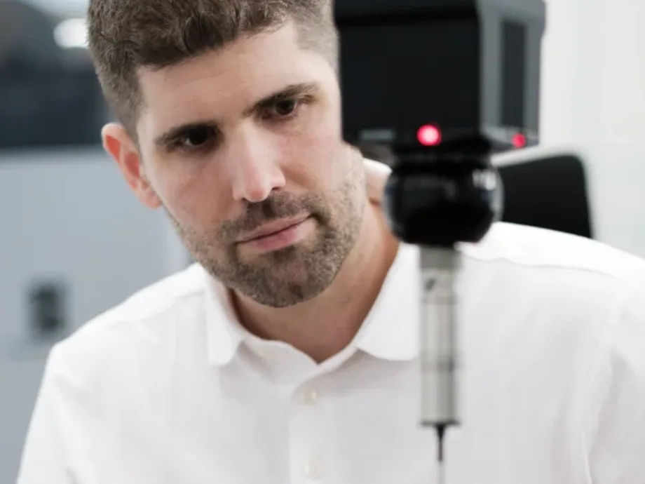
Christian Schärer in the measuring room
Christian Schärer
Owner and Managing Director · Standards committee Swissmem NK1
Prefer to talk first?
A 30-minute technical call about your drawing or measurement task. Free of charge, in English or German.
Pick a time →
Project enquiry
Send us your measurement task by email
Briefly describe the part and what should be inspected, and attach the drawing or CAD data — excerpts are fine. An NDA before the first file is available on request. You normally receive a reply within one working day, in English if you prefer.
Write to info@csl-imt.ch →
Or use the project form on the German contact page — it accepts uploads and an NDA option.
CSL Industrielle Messtechnik GmbH
Gewerbering 14 · 5610 Wohlen AG · Switzerland
Goods reception Monday–Friday, 08:00–17:00