Reducing production costs with ISO GPS: parallelism with the tangent feature
A tight tolerance is not automatically a functional tolerance. Where the function depends above all on the orientation of a seated plane, the tangent feature can deliberately separate orientation from the form of the real surface.
Unnecessarily restrictive drawing requirements can cause scrap, rework and costly root cause analyses even though a part fulfils its function. ISO GPS provides tools that let you formulate the specification closer to the actual function. One such tool is the tangent feature, indicated by the symbol  in the tolerance indicator.
The functional requirement: planar seating parallel to datum A
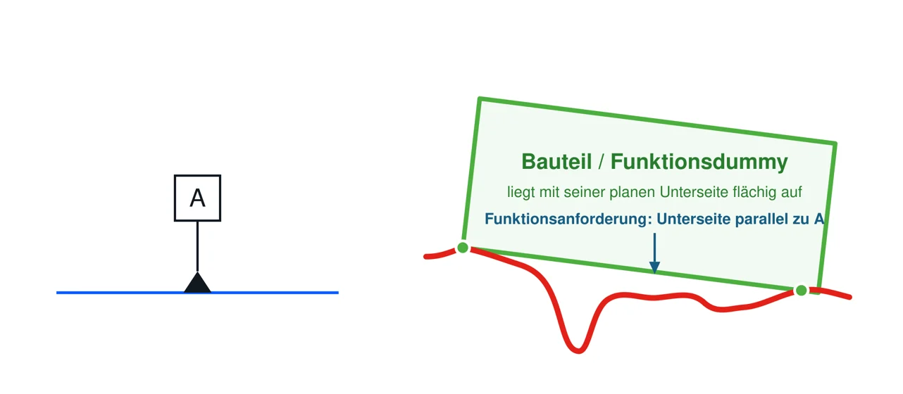
In the example, a part rests with its flat underside on the surface under consideration. What matters functionally is that the seated plane is oriented parallel to datum plane A. For this pure orientation function, local depressions on the side away from the material can be less critical than protruding areas, which determine the seating.
What ordinary surface parallelism requires
Without a special modifier, the parallelism specification applies to the extracted integral surface itself. For a planar surface referenced to a datum plane, that surface must lie entirely between two planes parallel to the datum plane. Their distance corresponds to the tolerance value.
Both the orientation and the form deviations of the surface therefore affect the result. Even a deep local depression can increase the required tolerance zone width, although in the specific application it may not impair the seating function at all.
For an identical extracted surface, identical surface extent, identical filtering and a comparable minimum zone evaluation, the surface parallelism value determined is at least as large as the flatness value. Parallelism therefore limits both the form and, in addition, the orientation relative to the datum plane. This statement applies to direct surface parallelism without the tangent feature.
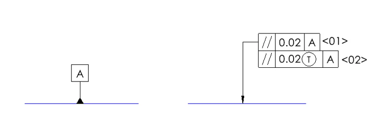 sits in the tolerance value field.
What the tangent feature changes
With the symbol , the specification no longer applies to the extracted surface itself but to a tangent feature associated with it. For a nominally planar surface, this toleranced feature is an ideal tangent plane.
ISO 1101 defines the tangent feature on the basis of the L2 norm, that is the least squares method, with the constraint that it lies outside the material of the non-ideal feature. The parallelism of this ideal tangent plane relative to datum A is then assessed.
It is not only the contact points that are evaluated: the extracted — and where applicable filtered — set of points enters into the association of the tangent feature. The material constraint ensures that the ideal feature lies on the material-free side. Depressions, however, do not themselves have to lie within the subsequent parallelism tolerance zone, because with the associated tangent plane is the toleranced feature.
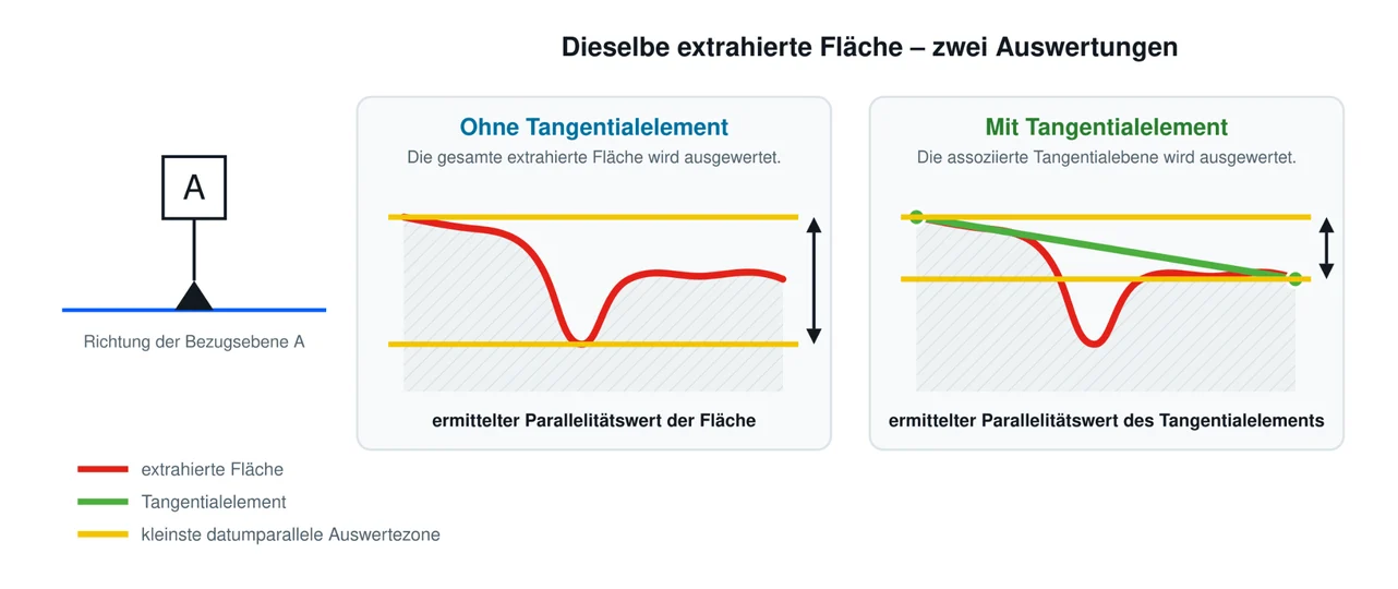 the associated tangent plane is assessed. A smaller parallelism value is possible but not guaranteed in principle.
Where the cost reduction potential arises
The tangent feature does not simply enlarge the numerical value of a tolerance. It changes which feature is toleranced. If this specification operator fits the function better, manufacturing can gain more usable latitude.
This can result in less scrap, less rework and more stable manufacturing processes. The prerequisite is always that the tangent plane correctly represents the real functional interface and that no other function is unintentionally released.
Limiting form deviation separately
Parallelism of the tangent feature does not directly limit the form of the real surface. Depressions must therefore not be dismissed as irrelevant across the board: they can affect the bearing area, stiffness, tightness, friction or contact stresses.
A combination of two specifications is often appropriate:
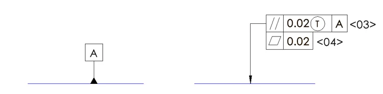
The set of points already captured can in principle be reused for both evaluations. This requires that the measurement strategy, surface extent, point density, filtering, evaluation algorithm and measurement uncertainty are suitable and documented for both specifications. A single 2D profile does not replace a 3D flatness evaluation. If only a defined line feature is considered, a separate straightness specification with an unambiguously defined intersection plane may be required.
Five questions before applying it
Conclusion
The symbol is still comparatively rare on industrial drawings. Yet it is worth considering wherever tight orientation or location tolerances are meant to represent a real contact or seating function. Applied correctly, the tangent feature prevents an unnecessary mixing of form and orientation and can thus enable more economical tolerances.
It is not, however, a blanket substitute for surface parallelism. Its use has to be derived from the function, complemented by a suitable limitation of form, and under control metrologically.