Skip to content
CSL Industrielle Messtechnik
DE|EN
+41 55 511 50 85 Request a quote →
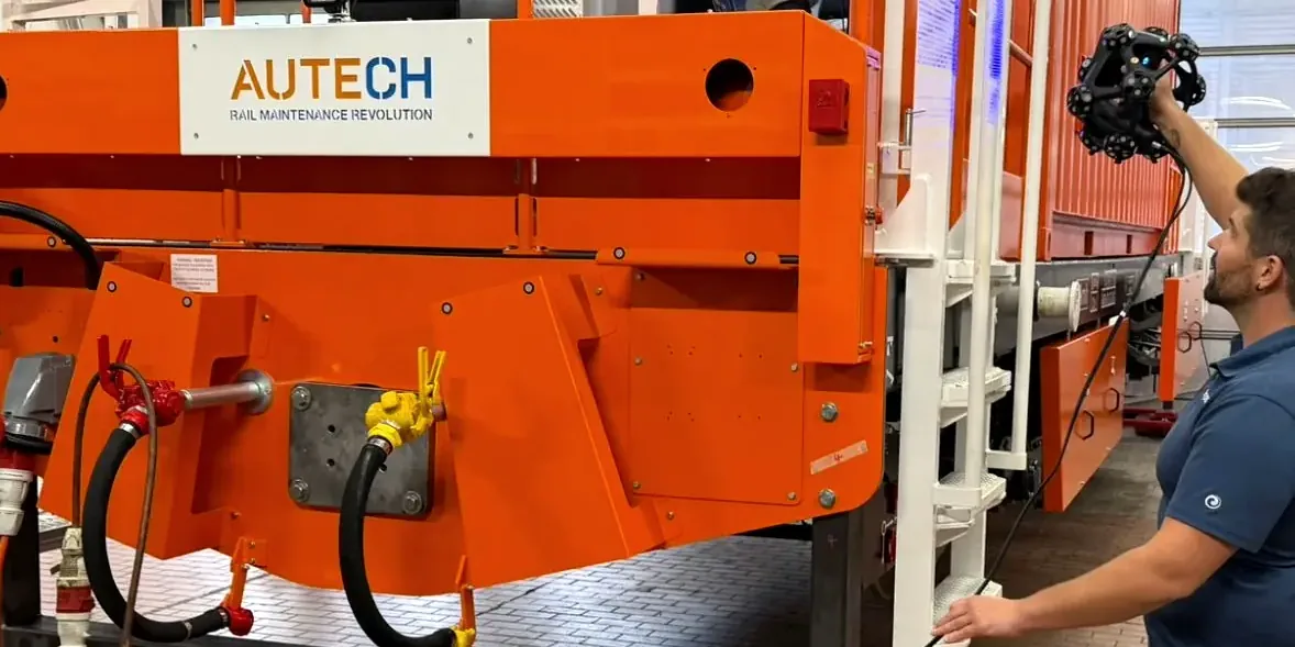
CSL metrology technician scanning an Autech AG rail vehicle with the Hexagon HYPERSCAN Super
Measurement method
3D laser scanning of large parts

Hexagon HYPERSCAN Super: capturing parts up to 12 m without targets, in one coordinate system. For the nominal-actual comparison against your CAD model and as a basis for reverse engineering.

Skip to content
DE|EN
+41 55 511 50 85 Request a quote →
CSL metrology technician scanning an Autech AG rail vehicle with the Hexagon HYPERSCAN Super
Measurement method

3D laser scanning of large parts

Hexagon HYPERSCAN Super: capturing parts up to 12 m without targets, in one coordinate system. For the nominal-actual comparison against your CAD model and as a basis for reverse engineering.

Describe your measurement task

What we use large-scale scanning for

If the part does not fit on the measuring table, the scanner comes to the part.

Comparing large parts, moulds and tools with the CAD model across the full surface
Checking welded assemblies, frames and housings for distortion and position
Digitising parts without a CAD model, as a basis for reverse engineering
Evaluating holes and edges directly from the scan
Performance data

Hexagon HYPERSCAN Super at CSL

Sensor
Hexagon HYPERSCAN Super: laser scanner with optical tracker, hand-guided, without targets on the part
Part size
0.1 to 12 m; larger parts by repositioning the tracker, still in one coordinate system
Volumetric accuracy
to VDI/VDE 2634-3, depending on the distance to the tracker: 0.05 mm up to 4.2 m · 0.075 mm up to 5.5 m · 0.09 mm up to 6.3 m · 0.14 mm up to 7 m; calibration in an ISO/IEC 17025 accredited laboratory
Scanner
resolution down to 0.02 mm · up to 8.3 million points per second · scan field up to 610 × 640 mm · holes to 0.03 mm, edges to 0.05 mm
Evaluation
Zeiss Inspect: nominal-actual comparison against your CAD model
Measurement uncertainty
the values above are manufacturer specifications from Hexagon; we clarify the measurement uncertainty for the specific inspection characteristic before accepting the order
Laser scan of a large assembly, with the optical tracker of the HYPERSCAN Super in the foreground

The scanner: modes and functions

Depending on the surface, the detail and the accessibility, we switch the scan mode without setting up the part again. All data ends up in the same coordinate system.

Schematic of the HYPERSCAN Super laser scanner The hand-guided scanner projects crossing blue laser lines onto the part. Cameras capture the lines, and the optical tracker follows the markers on the housing. The scanner evaluates edges and holes directly. Markers for the optical tracker Cameras capture the laser lines Laser lines 81 lines, up to 8.3 M points/s Hole to 0.03 mm Edge to 0.05 mm Working distance200–450 mm, up to 750 mm
Standard
81 crossing blue laser lines capture large surfaces quickly, up to 8.3 million points per second.
Single line
A single laser line reaches deep pockets, grooves and hidden areas.
Fine
34 laser lines at a working distance of 150 to 250 mm for small details at high resolution.
Edge detection
Edges and contours directly from the scan, to 0.05 mm.
Holes
The Hole Flash Capture mode captures holes, to 0.03 mm.
Long working distance
200 to 450 mm in Standard mode, up to 750 mm in Long Range mode for hard-to-reach areas.

Schematic representation. Values: manufacturer specifications from Hexagon.

Measuring volume of the tracker

The further the part is from the tracker, the larger the captured field. Accuracy decreases with distance; for tight tolerances, we place the tracker closer and measure in several positions.

Measuring volume of the Hexagon HYPERSCAN SuperThe measuring volume widens with the distance to the tracker: 1500 × 1000 mm at 1.5 m, 4000 × 4000 mm at 4.2 m, 4900 × 5200 mm at 5.5 m, 5500 × 6000 mm at 6.3 m and 6000 × 6600 mm at 7 m. The volumetric accuracy is 0.05 mm up to 4.2 m, 0.075 mm up to 5.5 m, 0.09 mm up to 6.3 m and 0.14 mm up to 7 m. 1500 1000 4000 4000 4900 5200 5500 6000 6000 6600 0 m 1.5 m 4.2 m 0.05 mm 5.5 m 0.075 mm 6.3 m 0.09 mm 7 m 0.14 mm Distance to the tracker Volumetric accuracy up to this distance Tracker

Measuring field width × height in mm. Manufacturer specifications from Hexagon.

Example: a 10 m part in four positions

The measuring field starts 1.5 m in front of the tracker and extends to 7 m. We therefore capture a longer part from several tracker positions. Four positions are enough here: at the ends, the tracker captures the end faces; on the long sides, it stands about 7 m away and captures each side up to the middle of the part. This places the part, including a 0.5 m margin all round, completely inside the measuring field. The measuring fields overlap. Distributed reference points on the part, each visible from several positions, link all positions into one coordinate system. Capturing the surface itself requires no targets.

Example: a 10 m long part in four tracker positions Top view of a fictitious part 10 m in length. The tracker stands in turn at both ends and on both long sides. The four measuring fields overlap; reference points on the part that are visible from several positions link the positions into one coordinate system. Part10 × 2.4 m 1 2 3 4 10 m 7 m 1Tracker position Field up to 7 m, overlap darker at least 0.5 m all round the part completely inside the measuring field Reference point on the part

Top view, to scale, fictitious part. We define the number and location of the positions for each part.

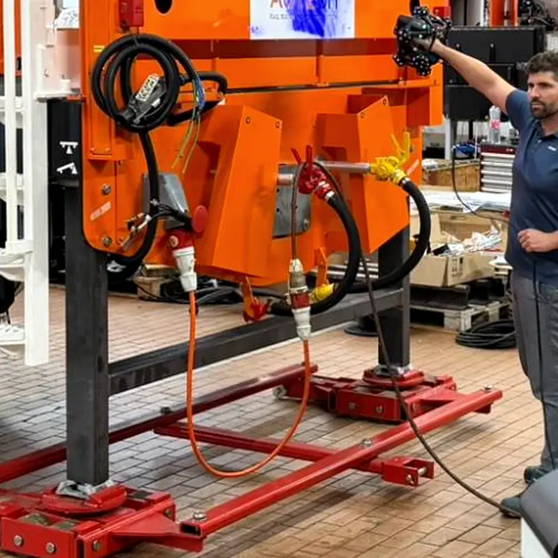
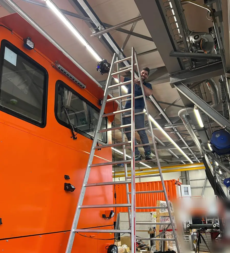
Laser scan of a large vehicle body: the metrology technician scans from the ladder up to the hall roof, with the tracker on its tripod at the bottom right

In use: up to the hall roof

The tracker stands on the floor and the scanner is guided by hand. This way, we also capture high surfaces of a large body in the same coordinate system, without repositioning the tracker, as long as the scanner stays within the measuring volume.

For parts that cannot be transported, we bring the system to you: on-site measurement.

Not sure which method fits your characteristic?
Mitutoyo logo
Official measurement service provider
of Mitutoyo Switzerland
ISO 9001 certification logo
ISO 9001:2015 certified
Certified quality management system
Logo of the Swiss Association for Standardization SNV
ISO GPS standardisation
Member of Swissmem NK1, ISO/TC 213
From practice
Autech AG logo
Rail vehicles3D laser scanningOn-site measurement
Reference · Autech AG, Rupperswil

Does the train fit through the tunnel?

Autech AG in Rupperswil builds large vehicles for the maintenance of railway lines. At the close of a project, a milestone required proof that the finished vehicle complies with the required clearance limits and fits through the tunnel. For this, CSL digitised the vehicle with the 3D laser scanner in the Autech hall. Autech then compared the scan data with the requirements in its CAD.

Situation
The vehicle was fully built and the project was about to close. The last milestone still missing was proof that the body and attachments lie within the permissible clearance limits.
Risk
A vehicle of this size does not fit on any measuring machine. The proof nevertheless requires the complete outer contour, including the areas high above the hall floor.
Method and strategy
CSL captured the vehicle on site with the Hexagon HYPERSCAN Super and the optical tracker, without targets on the vehicle. The handheld scanner was guided from the floor and from the ladder up to the hall roof. The data lies in one common coordinate system.
Handover
CSL delivered the digital image of the real vehicle. Autech carried out the comparison with the requirements itself, in its own CAD.
Closing note

For the proof at project completion, what counts is the vehicle as built. The laser scan brings it into the CAD as a data set, where the requirements already are.

Frequently asked

What customers ask about laser scanning large parts

How large can the part be?
The manufacturer recommends the HYPERSCAN Super for parts from 0.1 to 12 m. If the part is larger than one tracking volume, we reposition the tracker; the part remains in one coordinate system.
How accurate is the laser scan?
Hexagon specifies the volumetric accuracy to VDI/VDE 2634-3 depending on the distance to the tracker: 0.05 mm up to 4.2 m, 0.075 mm up to 5.5 m, 0.09 mm up to 6.3 m and 0.14 mm up to 7 m. What counts for the conformity decision is the measurement uncertainty for the specific inspection characteristic; we clarify this before accepting the order.
Does the part need targets?
No. An optical tracker follows the scanner, so no targets are needed on the part. This saves preparation and leaves the surface untouched.
What do I get as a result?
Depending on the task: the nominal-actual comparison as a false-colour image against your CAD model, sections and inspection characteristics, or the mesh for further use.
And if no CAD model exists?
Then the scan is the entry into reverse engineering: we reconstruct the surfaces and deliver a STEP model.
When do you scan with fringe projection instead of a laser?
For smaller parts and fine details, we use the Zeiss ATOS with fringe projection, with measurement uncertainties determined with calibrated reference parts. The laser scan shows its strength when the part is large or would need many takes.

Describe your measurement task.

Size, material and inspection characteristics are enough to start. Quotes are effort-based and transparent.
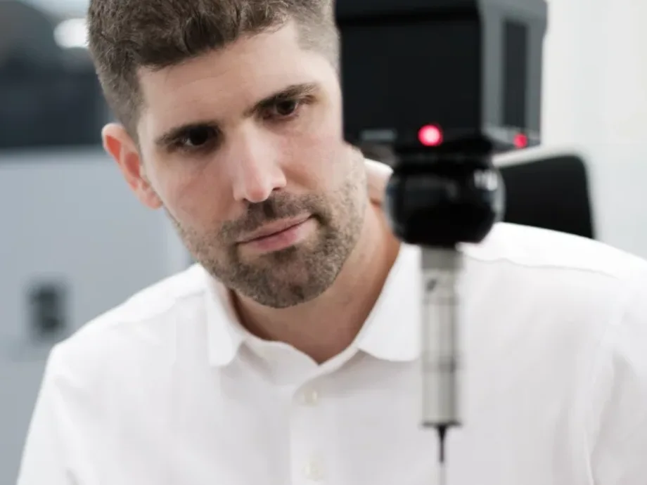
Christian Schärer in the measuring room
Christian Schärer
Owner and Managing Director · Standards committee Swissmem NK1
Prefer to talk first?
A 30-minute technical call about your drawing or measurement task. Free of charge, in English or German.
Pick a time →
Project enquiry
Send us your measurement task by email
Briefly describe the part and what should be inspected, and attach the drawing or CAD data. Excerpts are fine. An NDA before the first file is available on request. You normally receive a reply within one working day, in English if you prefer.
Write to info@csl-imt.ch →
Or use the project form on the German contact page, which accepts uploads and an NDA option.
CSL Industrielle Messtechnik GmbH
Gewerbering 14 · 5610 Wohlen AG · Switzerland
Goods reception Monday–Friday, 08:00–17:00