Stated measurement uncertainty: determination, checking and the influence of the stylus positions
Our page on tactile measurement states an expanded measurement uncertainty for every inspection characteristic. Each of those figures comes from a measurement on a calibrated workpiece. They hold for as long as they are re-measured at regular intervals.
MetrologyChristian Schärer · 27 August 2026
The values are determined to ISO 15530-3. A workpiece with calibrated characteristics is measured like a customer part, using the same program, the same stylus qualification and the same stylus positions. The deviation from the calibrated value, the scatter of the repeat measurements and the uncertainty of the calibration together give the expanded measurement uncertainty U at k = 2.
That ties the figure to a particular condition of the machine. A stylus knocked slightly out of position, a fixture with play, a temperature gradient in the room: each of these shifts the result, and the measuring system has no way of detecting it. Verifying against a calibrated workpiece is how such a shift becomes visible before it reaches an inspection report.
Key pointA stated measurement uncertainty holds until the next check.We check at defined intervals, after every collision and whenever something in the measuring sequence looks unusual.
When the check runs
Defined intervalsOn a fixed scheduleThe calibrated workpiece runs at set intervals, regardless of workload. That builds a series of comparable values in which slow drift shows up while it is still small.
After a collisionIncluding a light touchAny contact outside the measuring sequence stops the machine. Before release we requalify every affected stylus position and run the check measurement.
On anything unusualWhen the scatter does not fitUnfamiliar scatter in a repeat measurement, or a result that does not match the known production, is reason enough. No specific event is required.
In everyday use, checking and calibration are often treated as the same thing. They are two separate procedures. Acceptance and reverification testing to ISO 10360 establishes the performance characteristics of the machine, the length measurement error E and the probing error P; the result appears on the calibration certificate. The check belongs to the method itself. Alongside determining the task-specific measurement uncertainty on a calibrated workpiece, ISO 15530-3 also covers its reverification and interim check; the evaluation follows the GUM (ISO/IEC Guide 98-3). Interval and limit values are set by us as the operator, and what gets checked are exactly the values in the table further down.
Our check on a calibrated workpiece captures the same characteristics that are measured on the customer part, using the same program, the same probe configuration and the room conditions of our measuring laboratory. Its statement holds for this measuring task and for similar parts; it does not carry over to a characteristic with different geometry. Traceability comes from the calibration of the workpiece, the check itself establishes none.
What a check measurement shows
The measured deviation from the calibrated value is compared with the stated uncertainty. For the Ø50 mm diameter, U is 2.0 µm. As long as the deviation stays inside that band, the stated value is covered. Once it leaves the band, the value no longer applies to this inspection process, and the search for the cause starts before the next customer measurement.
One check measurement inside the band is enough for the confirmation. Where the result sits close to the edge of the band, or where there is a suspicion, we measure the workpiece several times. The series then shows whether the values scatter around the calibrated value or sit shifted to one side. A one-sided shift points to a systematic cause: a stylus position that needs requalifying, a changed fixture, a temperature gradient.
In the inspection report
The conformity decision is made against the tolerance without the measurement uncertainty being deducted. Where the uncertainty is known, we list it at the end of the report. Whether the customer deducts the uncertainty from the tolerance and works with tightened acceptance limits is the customer’s own decision. How well an inspection process holds up against a given tolerance is answered by a measurement process capability study.
The geometry dictates the stylus positions
On many parts the stylus cannot reach every surface from a single position. A bore across the main direction, a face inside a pocket, a characteristic on the back: the articulating head has to rotate before the surface can be probed. Those positions are set by the part.
Every position is qualified separately. Stylus qualification captures the dynamic behaviour of the styli in use and references the positions to each other against a standard, usually a precision ceramic sphere. Each position carries its own uncertainty into the result. For geometrical characteristics the uncertainty of establishing the datum is added, because datum and characteristic are often captured from different positions. For perpendicularity this raises U from 2.0 µm to 7.5 µm once datum and characteristic require three positions.
For the measurement strategy that means looking at accessibility before the program is written wherever the tolerance is tight. A different fixture that brings a characteristic within reach of one position achieves more than any fine tuning of the sequence. Where the geometry leaves no choice, the higher uncertainty belongs in the assessment of the characteristic.
Measurement uncertainty by characteristic on our Crysta-Apex S 776
Expanded measurement uncertainty U with a coverage factor of k = 2, evaluated with a calibrated workpiece to ISO 15530-3 and assessed to the GUM (ISO/IEC Guide 98-3). The coverage interval is roughly 95 percent. The number of stylus positions is stated because each position is qualified separately and adds its own uncertainty to the result. With several positions the uncertainty is therefore usually higher than with one. All values are rounded up to 0.5 µm.
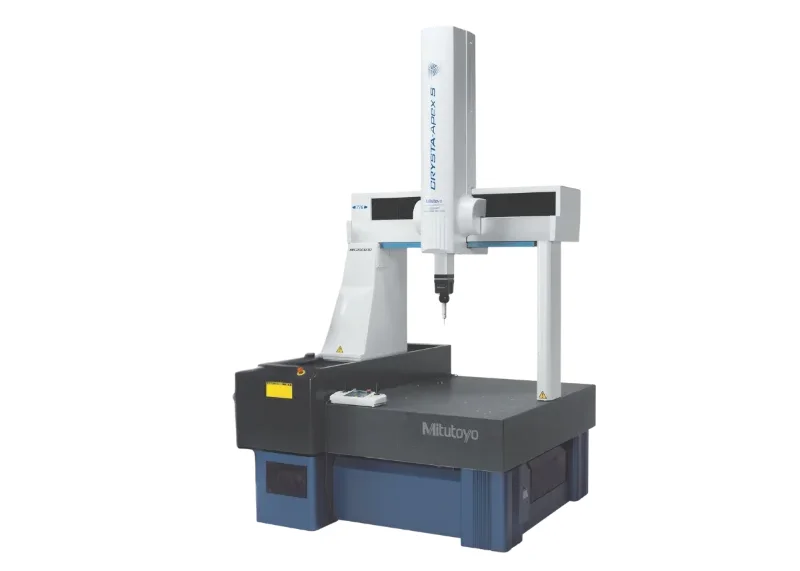
Mitutoyo Crysta-Apex S 776 · the coordinate measuring machine these values refer to
Size dimensions
Nominal
Stylus positions
U (k = 2)
↔
Distance
25 mm
1
3.0 µm
↔
Distance
100 mm
1
2.0 µm
↔
Distance
200 mm
1
3.0 µm
Ø
Diameter
Ø50 mm
1
2.0 µm
Ø
Diameter
Ø100 mm
1
2.0 µm
Form tolerances
Nominal
Stylus positions
U (k = 2)
Straightness
–
1
2.5 µm
Flatness
–
1
3.0 µm
Roundness
–
1
2.5 µm
Cylindricity
–
1
2.5 µm
Surface profile
–
2
9.5 µm
Run-out tolerances
Nominal
Stylus positions
U (k = 2)
Circular run-out
–
1
4.5 µm
Location tolerances
Nominal
Stylus positions
U (k = 2)
Position
–
1
5.0 µm
Position
–
3
5.0 µm
Concentricity
–
1
2.5 µm
Coaxiality
–
2
5.5 µm
Symmetry
–
3
6.0 µm
Orientation tolerances
Nominal
Stylus positions
U (k = 2)
Parallelism
–
1
2.0 µm
Parallelism
–
2
2.5 µm
Parallelism
–
3
2.5 µm
Perpendicularity
–
1
2.0 µm
Perpendicularity
–
2
5.0 µm
Perpendicularity
–
3
7.5 µm
Angularity
–
3
4.0 µm
Stated in micrometres. The measurement report gives the same figures in millimetres, where 2.5 µm appears as 0.002 5 mm. Where a measurement task calls for its own uncertainty budget, we calculate it for that task and state the result separately in the report. All measurements run in the temperature-controlled measuring room at the reference temperature of ISO 1. How the room is built and monitored is described on the measuring laboratory page.
The same table sits with the machine on the page for tactile measurement. When another measuring instrument joins the laboratory, it gets its own block there with the values from its own determination. We consider the study of measurement uncertainty valuable and carry it out wherever it brings value to the customer.
For practical use
When comparing figures from different laboratories, always read the number of stylus positions with them. A value for one position and a value for three positions describe different inspection processes.
After every collision, requalify all affected stylus positions, even when the contact hit a single position.
With tight geometrical tolerances, settle accessibility early. The number of positions is a property of the part and its fixture; the program only reproduces it.
Keep the check results. Only the series over time makes drift visible, and it is the evidence that the stated uncertainty holds.
Stating a measurement uncertainty is a statement about your own inspection process. Checking against a calibrated workpiece is the work that keeps that statement standing.
Project enquiry
A characteristic with a tight tolerance on hard-to-reach geometry? Send us the drawing — we assess inspectability and measurement strategy as part of the job.